Basic Soldering Guide – How to Solder Electronic Components
Basic Soldering Guide on How to Solder Electronic Components to Circuit Board (PCB).
Basic Soldering Guide on How to Solder Electronic Components to Printed Circuit Board (PCB). This is a Detailed and Complete Soldering Guide on Automatic Soldering for Mass Production and Hand Soldering for Rework and Repairing of PCB.

Table of Contents:
Basic Soldering Guide – Introduction

Soldering is basically a technique to join two metals using a third metal or alloy.
Proper soldering technique and quality of solder are the lifeline of any Solder Joint and PCB Assembly. Quality of solder and the soldering technique decides the life and performance of any electronic equipment, appliance or gadget.
In electronics PCB Manufacturing, Assembly and Rework, the metals to be joined are the leads of the electronic components (thru-hole or SMD) with the copper tracks on the PCB. The alloy used to join these two metals is solder which is basically tin-lead (Sn-Pb) or tin-silver-copper (Sn-Ag-Cu). Tin-lead solder is called leaded solder because of the lead present in it while the tin-silver-copper solder is called lead-free solder because no lead is present in it.
The solder is melted using either a wave soldering machine or a reflow oven or a normal soldering iron and this molten solder is then used to solder wires or electronic components on to the PCB or Printed Circuit Board. After assembly of electronic components the board is called PCB Assembly or PCBA (Printed Circuit Board Assembly)
Few other terms such as brazing and welding are often linked with soldering. But one should remember that soldering, brazing and welding are different from each other. Soldering is done using solder while brazing is done using a lower melting-temperature filler metal. In welding, the base metal also melts while joining two metals whereas this is not the case with soldering and brazing.
Let us now start this Basic Soldering Guide.
Soldering Material
Let us first discuss in detail about all the basic soldering material and consumables needed.
1. Flux
Flux plays a vital role in any soldering process and electronics PCB Manufacturing and assembly. Flux removes any oxide and prevents oxidation of metals and hence helps in better soldering quality. In Electronics PCB Assembly process, flux removes any oxide and impurities from the copper tracks on the PCB and oxides from the leads of the electronic components. These oxides are biggest resistance in good soldering joint and by removing these oxides, fluxes play a very vital role here.

There are basically three types of Flux used in soldering:
- R Type flux – These flux are Non-Activated and are used where there is least oxidation.
- RMA Type Flux – These are Rosin Mildly Activated Flux. These fluxes are more active than R-Type fluxes and are used at places where there is more oxidation.
- RA Type Flux – These are Rosin Activated Flux. These are very active flux and are used at places that have too much oxidation.
Some of the fluxes available are water-soluble. They get dissolved in water with no pollution. Also there are No-Clean Flux which require no cleaning after the soldering process.
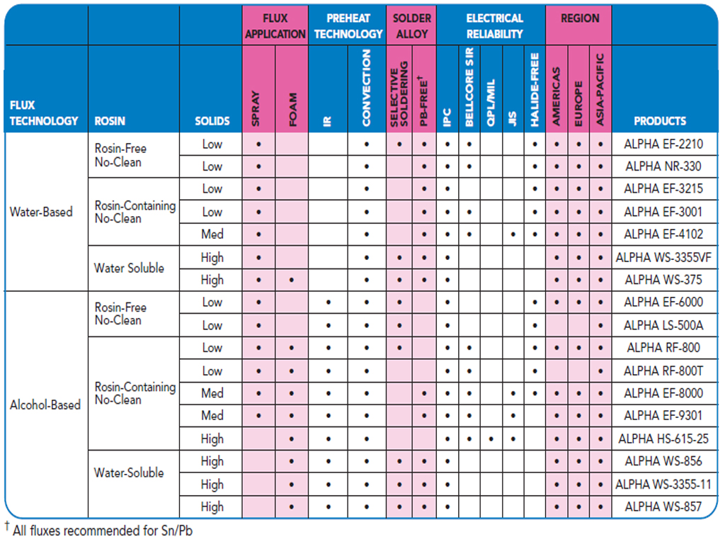
Types of Flux Used in Soldering
The type of flux to be used in soldering depends on various factors such as Type of PCB to be assembled, type of electronic components used, type of soldering machine and equipments used and the working environment.
2. Solder (Wire, Bar, Paste, Balls, Preforms)
Solder is the life and blood of any PCB Assembly. The quality of solder used during soldering and PCB assembly decides the life and performance of any electronic machine, equipment, appliance, mobile phone or gadget.

Different alloys of solder are available but the real ones are those that are eutectic. Eutectic solder is one that melts exactly at the temperature of 183 Degree Celsius (Sn/Pb). An alloy of tin and lead in the ratio 63/37 is eutectic and hence 63/37 tin-lead solder is called eutectic solder.
Solders that are non-eutectic will not change from solid to liquid at 183 Degree Celsius. They may remain semi-solid at this temperature. The nearest alloy to eutectic solder is tin-lead in the ratio 60/40. The favorite solder for electronic manufacturers have been 63/37 for years. It is still widely used across the world.
Because lead is harmful to the environment and human beings, the European Union imposed RoHS (Restriction of Hazardious Substances) and took the initiative to ban lead and other harmful substances from electronics. It has been decided to get rid of lead from solder and electronic components. Hence, more and more electronic companies in the world are shifting to RoHS. This has given rise to another form of solder called lead-free solder. This solder is called lead-free because there is no lead in it. Lead-free solder alloys melt around 250°C (482°F), depending on their composition. Most common lead-free alloy is tin / silver / copper in the ratio Sn96.5/Ag3.0/Cu0.5 (SAC). Lead-Free solder is also called “No-Lead” Solder.

Lead-Free Alloy Element Tolerances
Read: Lead-Free Soldering: A Safer Approach to PCB Assembly
Forms of solder:
Solder is available in various forms:
- Solder Wire
- Solder Bar
- Solder Preforms
- Solder Paste
- Solder Balls for BGA
Alpha Cookson is a leading manufacturer and supplier of all kinds of flux around the world.
3. Electronic Components
There are two types of electronic components – Active and Passive Electronic Components.
Active components are those that have gain or directionality. E.g. transistors, integrated circuits or ICs, logic gates.
Passive electronic components are those that do not have gain or directionality. They are also called Electrical elements or electrical components. E.g. resistors, capacitors, diodes, Inductors.
Again, electronic components can be in thru-hole or SMD (Surface Mount Devices or Chips).
Soldering Tools and Equipment
As explained above, soldering can be done the 3 ways:
- Wave Soldering: Wave soldering is done for mass production. Equipment and raw materials needed for wave soldering are – wave soldering machine, solder bar, flux, reflow checkers, dip tester, spray fluxers, flux controller.
- Reflow Soldering: Reflow Soldering is done for mass production and is used for SMD soldering . Equipments and raw material needed for reflow soldering are – Reflow Oven, Reflow checker, stencil printer, solder paste, flux.
- Hand Soldering: Hand soldering is done in small scale production and repair and rework of PCB. Equipments and raw materials needed in hand soldering are – Soldering iron, soldering station, solder wire, solder paste, flux, desoldering iron or desoldering station, tweezers, solder pot, hot air system, wrist straps, smoke absorbers, static eliminators, heating gun, pick-up tools, lead former, cutting tools, microscopes and magnifying lamps, solder balls, flux pen, desoldering braid or wick, desoldering pump or sppon, overcoat pen, esd material etc.
- BGA Soldering: Another form of electronic components are BGA or Ball Grid Array. They are special components and need special soldering. They do not have any leads, rather they use solder balls under the component. Because the solder balls have to be placed under the component and soldered, soldering of BGA becomes a very difficult task. BGA soldering need BGA soldering and rework systems and solder balls.
Wave Soldering Process
A wave soldering machine can be of different kinds, suitable for leaded wave soldering and lead-free wave soldering but all of them have the same mechanism. There are three zones in any wave soldering machine –
- Preheating zone: This zone preheats the PCB prior to soldering.
- Fluxing zone: This zone sprays flux on to the PCB.
- Soldering zone: The most important zone where there is molten solder.
There can also be a fourth zone zone called Cleaning Zone for cleaning of flux after the soldering is done.

Wave Soldering Process
A conveyor keeps moving across the plant. Employees inserts electronic components on to the PCB that keeps moving forward on the conveyor. Once all the components are in place, the PCB moves to the wave soldering machine passing through the different zones. Solder waves in the solder bath solders the components and the PCB moves out of the machine where it is cleaned and tested for any possible defect. If there is any defect, some rework / repair work is done by hand soldering.
Reflow Soldering Process
Reflow Soldering uses SMT (Surface Mount Technology) to solder SMD (Surface Mount Devices) on to the PCB. In Reflow soldering there are four stages –
- Preheat
- Thermal soak
- Reflow; and
- Cooling.

In this process solder paste is printed on the track of the circuit board where the component is to be soldered. Printing of the solder paste can be done using a solder paste dispenser or through stencil printer. This board with solder paste and components of the paste is then passed through a reflow oven where the components get soldered to the broad. The board is then tested for any defect and if there is any defect, rework and repair is done using hot air systems.
Hand Soldering Process
Hand soldering is basically done for small-scale manufacturing or repair and rework. Hand Soldering for thru-hole components is done using a soldering iron or a soldering station.
Hand soldering of SMD components is done using Hot Air Pencils or Hot Air Rework Blower. Hand soldering of thru-hole components is easier as compared to SMD Soldering.
Video: Hand Soldering Tutorial
Basic Soldering Guide : Key Points to Note
- Always keep the iron tip coated with a thin layer of solder. (Read: How to Clean and Tin Soldering Iron Tip)
- Use fluxes that are mild as possible but still provide a strong solder joint.
- Keep temperature as low as possible while maintaining enough temperature to quickly solder a joint (2 to 3 seconds max for electronic soldering).
- Match the tips size to the work.
- Use a tip with shortest reach possible for maximum efficiency.
SMD Hand Soldering Process
- Method 1 – Pin by pin method Used for: Two-pin SMD components (0805 caps & res), pitches >= 0.0315″ in Small Outline Package, (T)QFP and SOT (Mini 3P).
- Method 2 – Flood and suck method Used for : pitches <= 0.0315″ in Small Outline Package and (T)QFP
- Method 3 – Solder paste method Used for: BGA, MLF / MLA packages; where the pins are underneath the part and inaccessible.
Read: Surface Mount Soldering Guide – SMD Soldering
PCB Assembly Process Flow Chart (PCBA Process)

PCB Assembly Process Flow Chart (PCBA Process)
SMT PCB Assembly Process
Final Words
I hope you found this Basic Soldering Guide useful. If you have any doubts or questions, feel free to ask below in the comment section.
FAQs: How to Solder Electronic Components
What tools do I need for basic soldering?
You will need a soldering iron, solder wire, soldering stand, soldering flux, and a sponge or brass wire cleaner for cleaning the soldering iron tip. Safety gear like safety glasses and heat-resistant gloves are also recommended.
How do I solder electronic components?
First, heat the soldering iron to the appropriate temperature for your solder and components. Clean the iron's tip, then touch the tip to the joint where the component and the board meet. Feed a small amount of solder to the joint, allowing it to flow evenly. Remove the iron and let the joint cool without moving the components.
What are common soldering mistakes to avoid?
Avoid these mistakes:
- Using too much solder,
- Not cleaning the iron's tip,
- Overheating components, and creating "cold joints" (dull and lumpy solder joints).
- Avoid breathing in solder fumes by working in a well-ventilated area.
Can I desolder or remove soldered components?
Yes, you can desolder components. Use a desoldering pump or desoldering wick to remove excess solder. Heat the joint with the soldering iron and then use the desoldering tool to remove the molten solder. Once the solder is removed, you can gently lift the component off the board.
Related Articles
- Soldering Station Guide
- Pin Hole and Blow Hole Wave Soldering Defect and Remedy
- Cold Solder Joint
- Soldering Station in India
- Top Electronic Companies in USA
- Soldering Station in India
- Electronic Circuits for Beginners
- Electronic Materials and Consumables List
- Top 10 Electronic Components Manufacturers in the World
- PCB Assembly Machines and Tools
- Best Selective Soldering Machine & Selective Soldering Process
- SMT Machine and SMT Machine Manufacturers


There is also this flux cored solder.. With this you don’t have to use additional flux.. And I think the solder works more efficiently that way.. You can include it in your list..